
Modulation Index Measurement in TV Signal Processing
In the realm of television signal transmission, ensuring the correct modulation index—the ratio of the modulating signal's amplitude to the carrier frequency's amplitude—is critical for image quality and signal stability. Achieving the precise balance requires a systematic approach to measurement and adjustment using specific reference signals.
The Measurement Process
To begin the adjustment of the modulation index, a maximum level Composite Video Signal (CVS) of 1000 mV, typically in a sawtooth waveform, is applied to the modulator. This modulated Radio Frequency (RF) signal is then fed into a professional TV receiver.
Professional receivers include a specialized feature that allows the RF signal to be switched off for a brief interval during each consecutive line. During this specific window, the modulation ratio effectively drops to 0%.
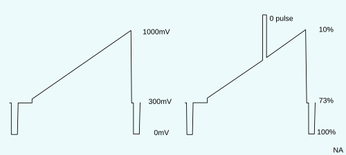
When this interruption occurs across all lines in a frame, it manifests as a vertical white bar on a visual monitor. This visual marker is known as the 0 reference pulse (or 0 pulse). On an oscillogram, the 0 pulse appears as a signal level that exceeds the maximum level of the CVS.
Calculating and Adjusting the Index
The modulation index is determined by comparing the 0 reference pulse to the sync tip (the lowest point of the synchronization signal). By defining the level difference between the sync tip and the 0 pulse as 100%, the maximum CVS is typically set to 10% or 12.5% of that range.
Adjusting the modulation index is a straightforward process: it is achieved by modifying the level of the modulating signal (CVS) at the input of the modulator until the desired percentage is reached.
Key Facts
- Input Level: Maximum CVS input is 1000 mV.
- Reference Marker: The 0 reference pulse appears as a vertical white bar on a monitor.
- 0 Pulse Characteristics: It represents a 0% modulation ratio and exceeds the maximum CVS level.
- Target Range: Maximum CVS should be 10% to 12.5% of the difference between the sync tip and the 0 pulse.
- Adjustment Method: The index is tuned by adjusting the CVS input level at the modulator.
| Parameter | Value/Description |
|---|---|
| Maximum CVS Input | 1000 mV (Sawtooth) |
| 0 Pulse Modulation Ratio | 0% |
| Visual Indicator | Vertical white bar |
| Standard CVS Percentage | 10% to 12.5% |
| Reference Baseline | Difference between sync tip and 0 pulse |
Frequently Asked Questions
What is a 0 reference pulse?
A 0 reference pulse is a signal created by briefly switching off the RF signal in each line of a frame, resulting in a 0% modulation ratio and appearing as a vertical white bar on a visual monitor.
How is the modulation index adjusted?
The modulation index is adjusted by changing the level of the modulating signal (CVS) at the input of the modulator.
What is the standard input level for CVS during this measurement?
The maximum level CVS applied to the modulator is 1000 mV.
How is the 100% reference level defined in this process?
The 100% reference is defined as the level difference between the sync tip and the 0 reference pulse.
What is the target percentage for the maximum CVS?
The maximum CVS should be adjusted to be 10% or 12.5% of the difference between the sync tip and the 0 pulse.