
Parity Bits and Error Detection in Data Transmission
In the world of digital communication, ensuring that data arrives exactly as it was sent is a constant challenge. Electrical noise and interference can cause a bit flip—a phenomenon where a binary 1 becomes a 0, or vice versa. To combat this, engineers use error detection mechanisms, one of the simplest and most efficient being the parity bit.
A parity bit is a single bit added to a string of binary code to ensure that the total number of 1-bits in the string is either even or odd. This simple addition allows the receiving system to detect if a transmission error has occurred during transit.
Key Facts
- Parity bits can detect errors but cannot correct them.
- They are only capable of detecting an odd number of bit errors.
- The system requires the entire corrupted data packet to be discarded and retransmitted.
- Parity is computationally inexpensive, requiring only a few XOR gates (exclusive OR gates) to generate.
- Commonly used in 7-bit ASCII character transmissions, where the 8th bit serves as the parity bit.
How Parity Works: Even vs. Odd
There are two primary types of parity schemes: even and odd. The choice depends on the protocol being used, but the logic remains the same: the sender calculates a bit to meet a specific requirement, and the receiver checks if that requirement is still met.
Even Parity
In an even parity scheme, the parity bit is set so that the total number of 1s in the transmitted block is an even number. For example, if Alice wants to send the 4-bit message 1001, she counts two 1s. Since 2 is already even, the parity bit is 0, and she sends 10010. If she wanted to send 1011 (three 1s), she would add a parity bit of 1 to make the total four, sending 10111.
Odd Parity
In an odd parity scheme, the parity bit is set so that the total number of 1s is odd. Using the same example, for the message 1001 (two 1s), Alice would add a parity bit of 1 to make the total three, sending 10011. For 1011 (three 1s), she would add a 0, sending 10110.
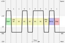
Detecting Transmission Errors
When the receiver (Bob) gets the data, he performs the same parity calculation. If the result does not match the agreed-upon scheme, he knows an error occurred.
Consider a scenario using even parity where Alice sends 10010. If a transmission error flips the second bit, Bob receives 11010. Bob calculates the parity: 1+1+0+1+0 = 3. Because 3 is an odd number and the system expects even parity, Bob reports an incorrect transmission.
This detection also works if the parity bit itself is the bit that gets corrupted. If Alice sends 10010 and Bob receives 10011, the total count of 1s becomes 3, triggering a parity error.
Limitations of Parity Schemes
While efficient, parity bits have a critical weakness: they can only detect an odd number of bit errors. If an even number of bits are flipped, the error goes undetected because the overall parity remains the same.
For instance, if Alice sends 10010 (even parity) and two bits are corrupted during transmission, Bob might receive 11011. Bob calculates the parity: 1+1+0+1+1 = 4. Since 4 is even, Bob assumes the transmission was successful, even though the data is actually corrupt.
Because parity cannot identify which specific bit is wrong, it cannot correct the data. In noisy environments, this can lead to frequent retransmissions, potentially delaying communication indefinitely. For scenarios requiring actual error correction, more complex systems like the Hamming code are used.
| Scenario | Sent Data | Received Data | Parity Result | Outcome |
|---|---|---|---|---|
| Successful | 10010 | 10010 | Even | Correct |
| Single Bit Error | 10010 | 11010 | Odd | Error Detected |
| Parity Bit Error | 10010 | 10011 | Odd | Error Detected |
| Double Bit Error | 10010 | 11011 | Even | Error Undetected |
Frequently Asked Questions
Can a parity bit fix a corrupted piece of data?
No, a parity bit is strictly for error detection. It can tell the receiver that an error occurred, but it cannot determine which bit was flipped. Consequently, the corrupted data must be discarded and retransmitted.
What happens if two bits are flipped in a single transmission?
If an even number of bits (such as two) are flipped, the parity remains unchanged. The receiver will calculate the expected parity and incorrectly assume the data is valid, failing to detect the corruption.
Why is parity still used if it cannot correct errors?
Parity is used because it is extremely simple and computationally cheap. It requires very little overhead (only one bit) and can be implemented using a small number of XOR gates, making it ideal for simple systems.
How does parity relate to ASCII characters?
Standard ASCII characters use 7 bits. In many transmission systems, the 8th bit of a byte is utilized as a parity bit to ensure the integrity of the character being sent.
What is the difference between even and odd parity?
Even parity ensures the total number of 1s in the data block is even, while odd parity ensures the total number of 1s is odd. Both methods are equally effective at detecting single-bit errors.